Steppers
Steppers are an unsual sort of motor, because they take a special pulsed signal and for each pulse, the move one step, which is usually 1/200 of a rotation. So, you have to send 200 pulses to move the motor around once. This allows for very accutate positioning.
Our stepper motor is a very small one, and it also has a 1 to 10 gearbox, which means that we need to send 2,000 pulses for the shaft to move one rotation.
Connections
Connect the stepper motor and stepper driver board like this:
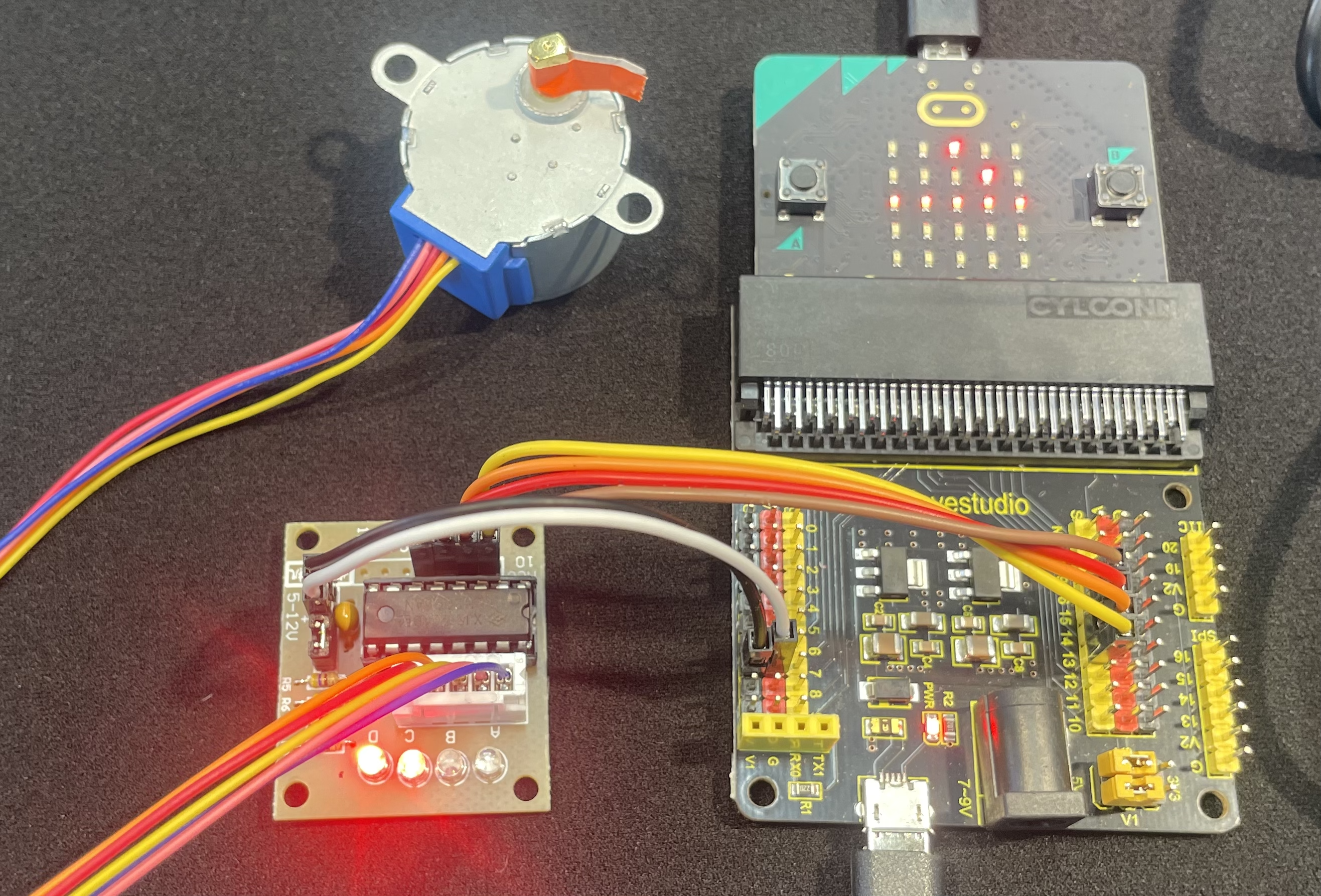
Connect the Micro:bit breakout to the stepper driver:
Pin 13 yellow to IN1
Pin 14 yellow to IN2
Pin 15 yellow to IN3
Pin 16 yellow to IN4
Connect the white plug of the stepper motor to the white socket on the stepper driver.
Connect the stepper driver to power. For the power connection, you can use any of the red and black pins, bu we will use Pin 0.
Pin 0 black to black wire to “5-12 v -” on the driver board
Pin 0 red to white wire to “5-12 v +” on the driver board
( Remember that the positive power is marked with a + and is usually red, but we will have a white wire for positive. The negative is marked with - and is usually black, but for our circuits, it is always also connected to ground. )
Program
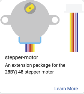
Create a new Makecode project and add the stepper extension.
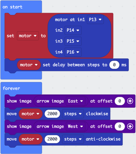
Then, enter in this program:
You can also import this program from https://github.com/League-Microbit/stepper.
After you download the program, you should see the shaft of the stepper motor moving back and forth.
What is it doing?
You will notice that the LEDs on the board seem to be blinking, but they are blinking too fast to see the pattern. Let’s slow it down.
In the block “set delay between steps to” change th value from 0ms to 500ms. The “ms” means “miliseconds” or 1/1000 of a second. So, 500/1000 seconds is half a second.
After making the change, download the program again and observe the LEDs. Now that we’ve increased the delay, we can see the patterns of the LEDs, which indicate which magnetic coils are being activated to move the motor one direction or the other. Let’s figure out what these lights mean by looking at the wiring diagram for the motor.

Image from of Random Nerd Tutorials
The squiggly parts of the diagram are magnetic coils, which are just electromagnets. The common connection for all of the coils is pin 5. Each of the leds indicates that power is being applied to one of the pins, and when that happens, it turns on one of the elctromagnets.
The LED pattern is:
1 & 2
2 & 3
3 & 4
4 & 1
Just like an electromagnet picks up paperclips or nails, the electromagnetic coils in the stepper attract the rotor, which turns a bit. By energizing these coils in order, we can make the rotating rotor “chase” the elecctromagnets, causing it to rotate.
If you want to understand how this works in more detail, this video will show you what is inside the stepper motor.
Learn More
Here is a video about how stepper motors work.
Notes: This step patterns is full stepping