Signals and Power
To control motors, we need to generate signals. A “signal” is an electrical impulse that conveys information.
Imagine that you are pluging in a lamp, and the lamp switch is on. When you plug it in, the light lights up. Then you unplug it and the light goes out. Ah ha!
If you have a neighbor friend who knows Morse code, you might send a message. You plug the light in sometimes for a short time, or sometimes for a long time. If “-” means you leave the light in for a long time ( 1 second ) and “.” means you leave the light plug in for a short time ( 1/2 second. ) Pluging and unplugging, you can send this message:
.-.. . - .----. ... /
.--. .-.. .- -.-- /
-..- -... --- -..- .-.-.- /
-... .-. .. -. --./
 - .- -.- .. ... .-.-.- /
A few minutes later, your friend arrives at your house, with your favorite snack.
( Cut and paste the Morse code into the Morse Code Translator to decode the message. )
When you pluged the light into the socket, you produced a voltage at the light bulb. And when you unpluged it, you removed the voltage. A voltage is like water pressure in a hose, but with electrons instead of water, and a lot of electronics use voltage to convey information, just like you did when you sent the message to your friend with the light. So, you can also change the voltage on a wire to send a signal.
That is what we are going to do now: change the voltage on a wire to send a signal.
Connecting Power
Before we hook up some motors, we need to understand a bit aobut ewlecctrical power.
When you are connecting circuits together, you will need to not only need to connect the signals, you will also have to supply power for running the circuit. Some circuits, such as the Micro:bit, get their power from the USB connection, but other circuits will need to be connected to a power line.
There are several types of connections we will have to ensure that we have:
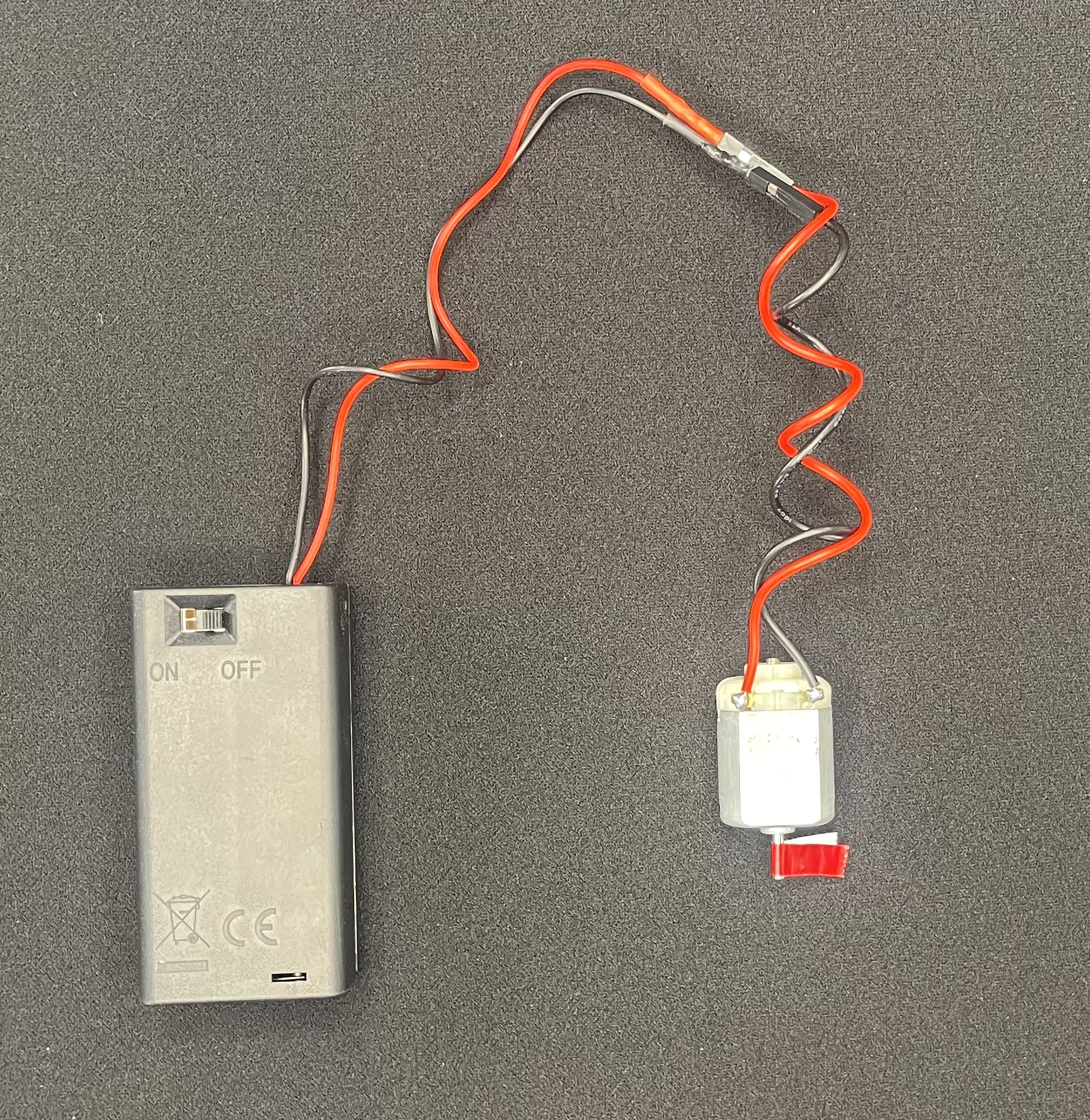
Positive power. This is often marked with a “+” or “Vcc” and the color is usually red. ( However, in this kit, our power supply wire is white. )
Negative Power. This wire is often marked with a “-” and the color is usually black. It is often connected to ground.
Ground. Ground is a neutral wire, it always has 0 volts. It will be labeled “G” or “Gnd” and it’s color is green. It is often connected to the power supply negative.
For the types of circuits we will work on, the negative is always connected to ground. Because the ground and negative are always connected, the color for these connections are black, not green/
BTW, the ground connection is called “ground” because it is literally connected to a stake in the ground. The ground line of our circuits are connected to the ground wire of the building’s electrical connection. ( If an electrical wall socket looks like a face, the ground connection is the mouth. ) The building ground wire will go to the electrical panel of the building, where it will be connected to either a long copper spike that is driven into the ground, or to a copper water pipe that is in the ground.
Program
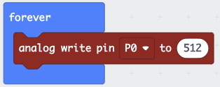
Using the Makecode Editor, write this program. If you are still editing the old program, click  to go back to the main screen, then click + New Project to start a new project. Call the project something like “Analog Write” or “Signals”.
The analog write block is in the “Advanced >> Pins “ section of the block menu in the middle of the screen.
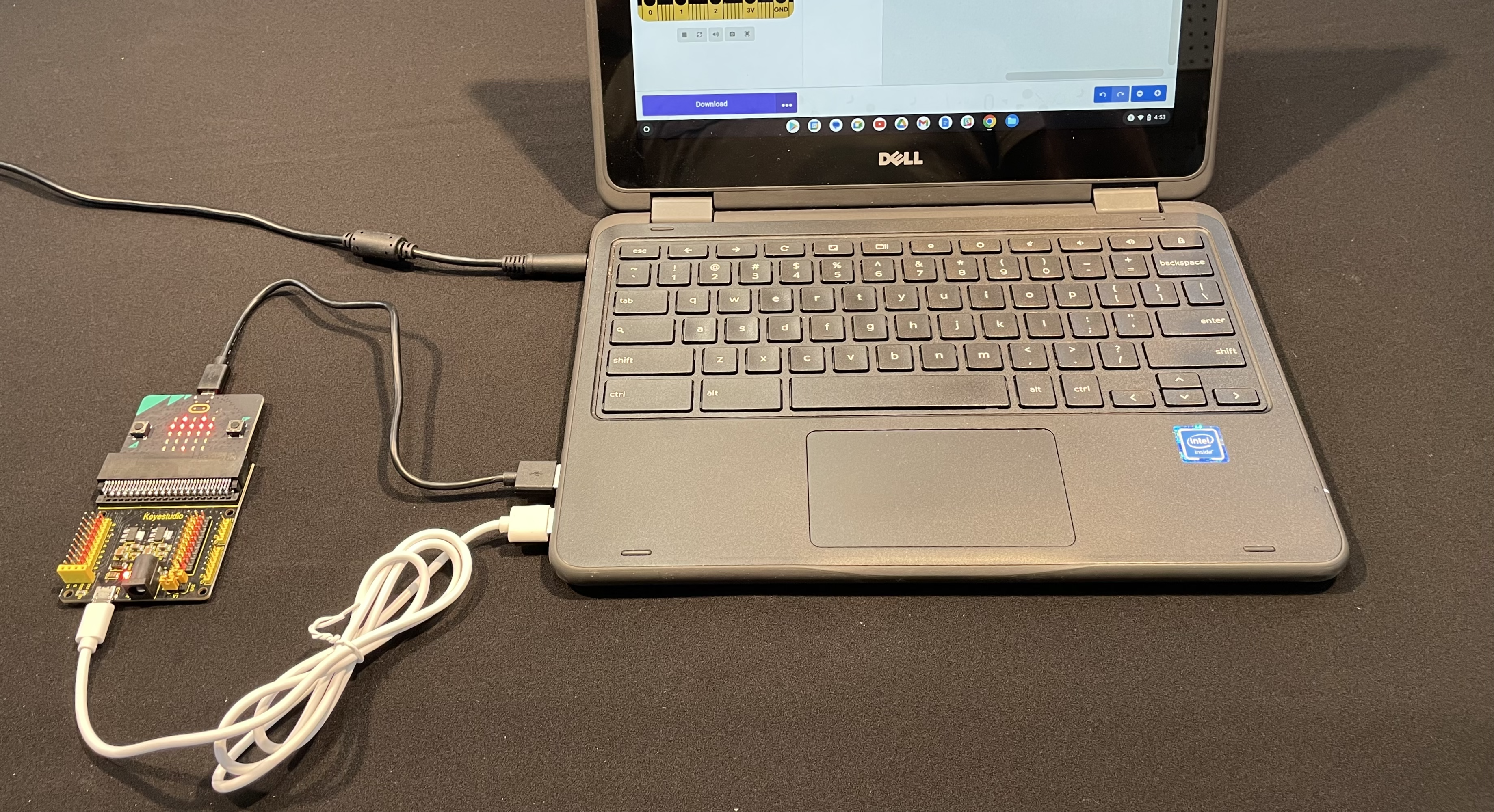
Hardware Setup
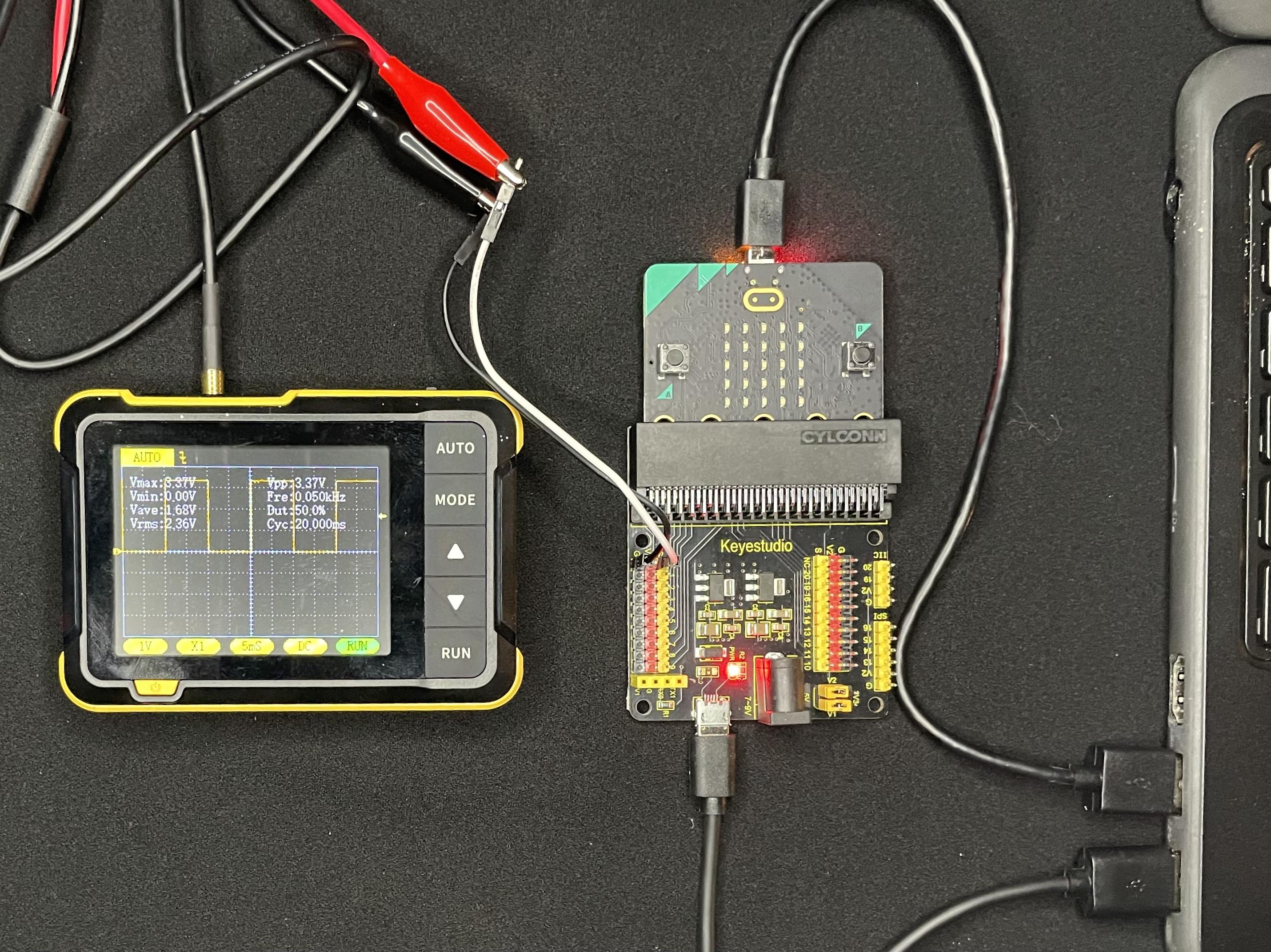
Driving a motor requires a lot of power, more than the Microbit can supply though its pins. So, we will attach a breakout board that has an extra power supply. This board will require another USB port. When these parts are assembled, it will look like this:
Notice that the program says it will write to “Pin P0”. The Pin “P0” is the yellow pin labeled ‘0’ on the breakout board, in the upper left. The yellow pins are the signal pins. On the top of the row, they are labeled with ‘S’, for signal.
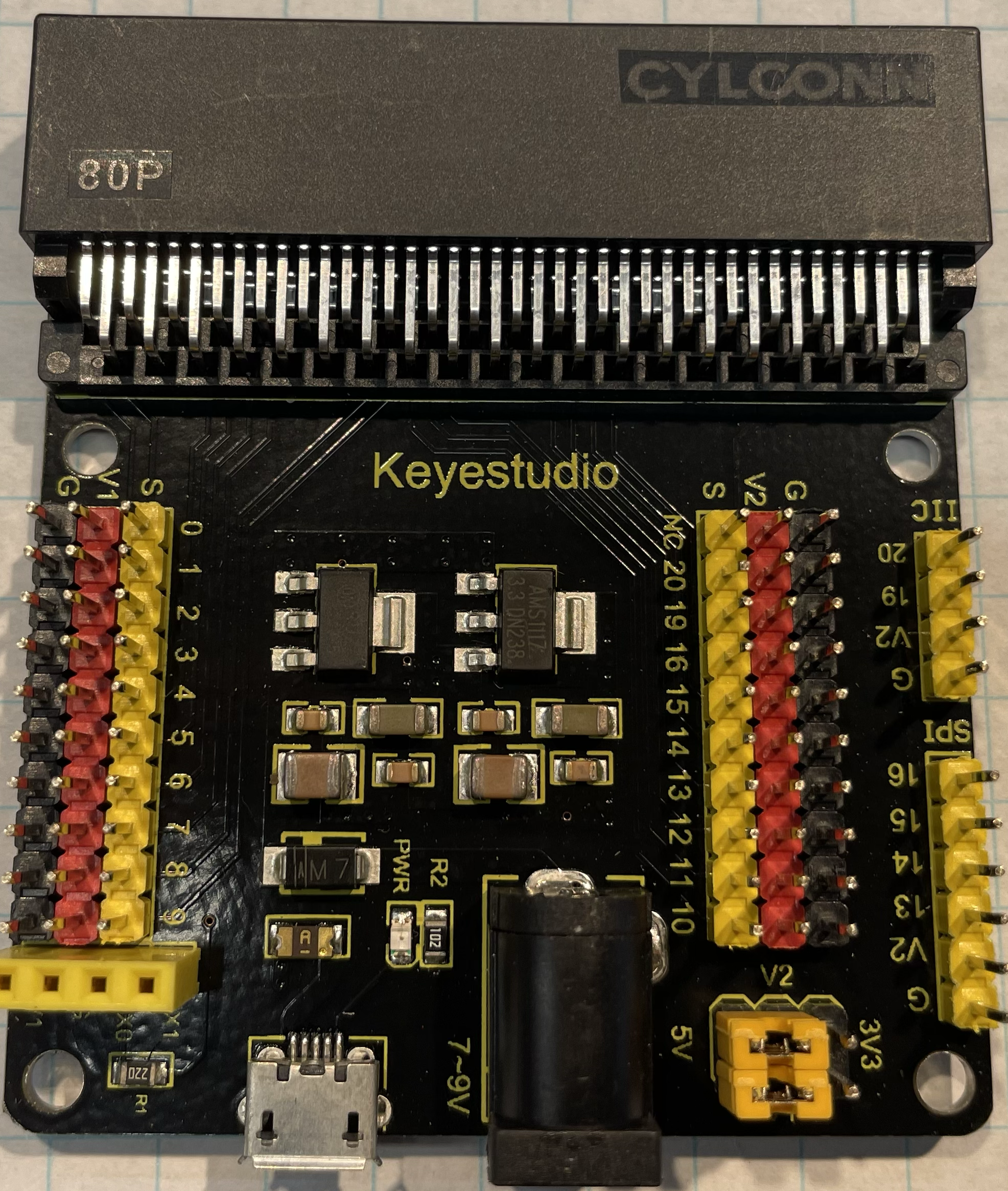
Next to the yellow signal pins are the red power pins. This row is labeled on the top with ‘V1’ on the left, and ‘V2’ on the right. The two labels are because these power rails can be set to different voltages. Look in the lower right for six pins and two yellow jumpers with ‘V1’, ‘V2’, ‘5V’ and ‘3V3’ printed around them. You can move the jumpers to make V1 and V2 either 5 volts or 3.3 volts. Your board should be set to 5v.
Now let’s connect the oscilloscope. Connect two Dupont wires ( which have the black square ends ) to the P0 signal ( yellow ) and P0 ground ( black ). Then connect the aligator clips to the other end of the Dupont wires, and plug the aligator clips into the osciloscope.
After you make these connections, trace the black alilgator clip through the Dupont wire to the black P0 pin, and trace the red aligator click through the Dupont wire to the yellow P0 pin.
Oscilloscope Trace
Next:
Turn on the osciloscope
Download and run your program
Press the “Auto” button on the oscilloscope.
When you run the program and look at the signal, this is what you will see:
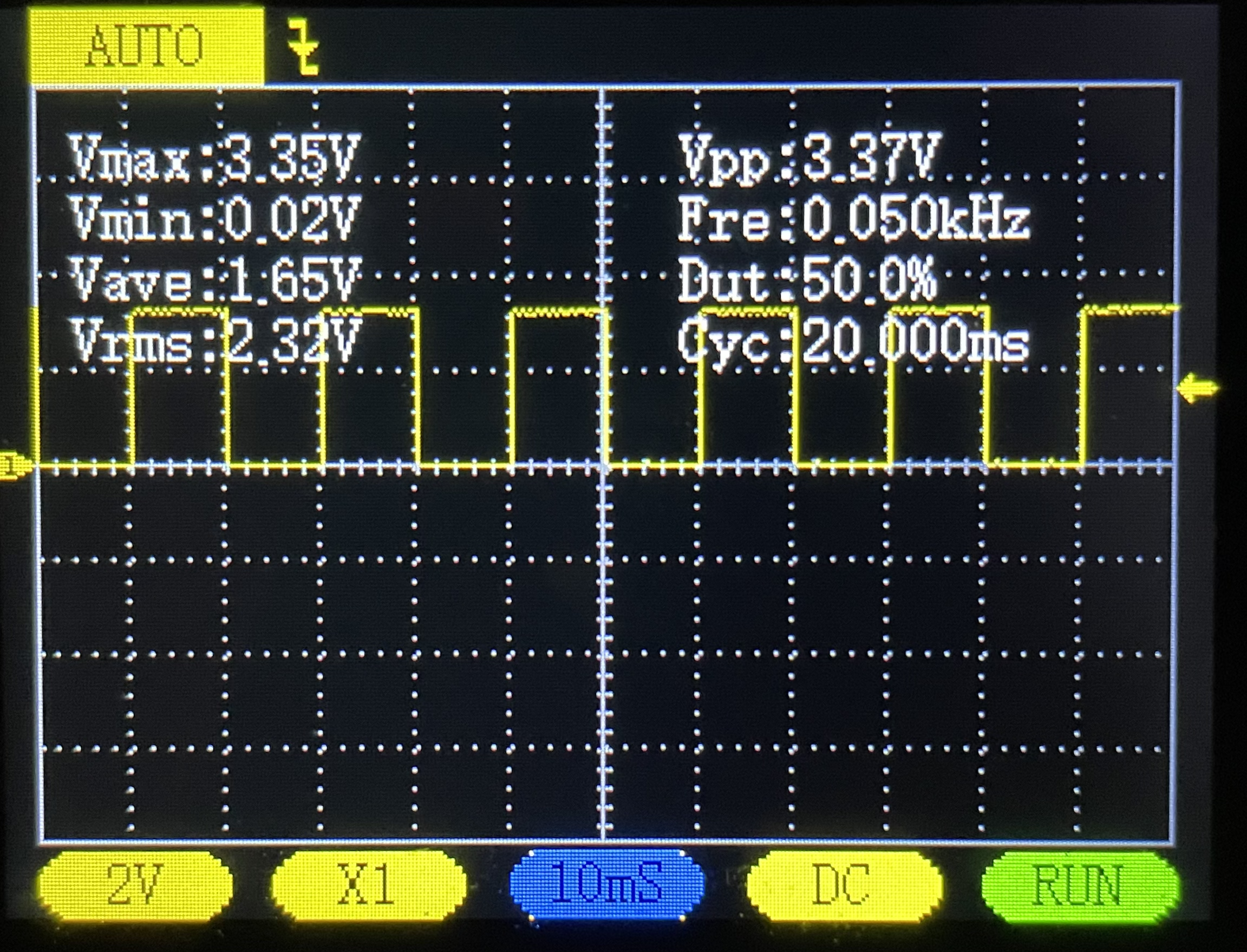
The yellow line that goes up and down is the voltage on the P0 pin of the
Micro:bit. The bottom of the line is at 0 volts, and the top of the line is at
about 3.3V. ( You can see these voltages in the white text in the background,
for Vmax and Vmin )
The “Dut” text in the background is the “Duty Cycle”, which is the percentage of the time that the signal is at a high voltage. It should be 50%, because the value we set in the program , 512, is 50% of the way between the min value for the analog value of 0, and the maximum value of 1024.
We will be using this signal, which is called a “Square Wave” for controlling the motors.
Changing the Duty Cycle
Unlike the signal un our oscilloscope, the duty cycle of a motor control signal will change, to change the speed or position of the motor. Lets update our program to change the signal.
Switch your program to Python mode from the switch at the top of the screen, then edit the program to this:
def on_forever():
    for index in range(5):
        pins.analog_write_pin(AnalogPin.P0, index)
        basic.pause(10)
basic.forever(on_forever)
After making this change, you will see the the duty cycle change from 0% to 100%.