Brush Motors
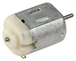
One of the most common types of motors is the brushed continuous rotation DC motor. These motors use the magnetic field created when electricity moves through a wire to push against a permanent magnet. Motors come in a range of sizes, from microscopically tiny to enormous, but we will be using a common type of low voltage motors that is small, simple and inexpensive:
These motors will require a lot more power than our microcontroller can provide. Additionally, for use in a robot, we’d probably want the motor to be able to turn both forward and backwards, and turn at different speeds. A driver board can help us with all of these problems.
Our motor driver board has a cuircuit called an H-Bridge, because the circuit is composed of switches in the shape of an “H”
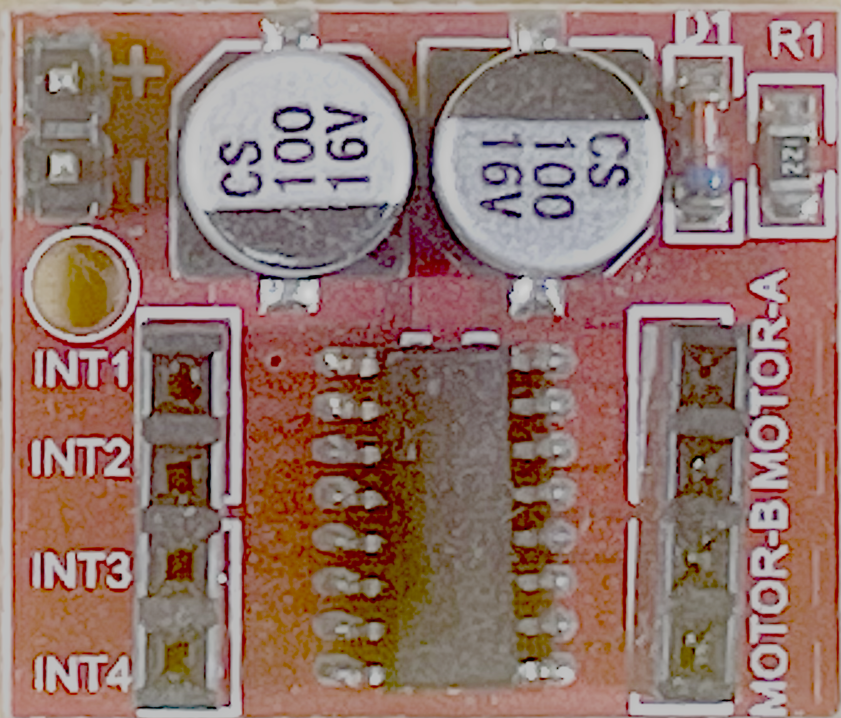
This driver has two H-bridges on it. The inputs INT1 and INT2 control
Motor A, and INT3 and INT4 control Motor B.
When we turn pin INT1 on and INT2 off, the circuit turns on switches S1
and S4, which causes current to flow forward through the motor and the motor
turns forward. When INT1 is off and INT2 is on, the circuit turns on switch
S2 and S3, the current flows backwards through the motor, and the motor turns
backwards.
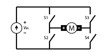
Image from of Driving a motor with the L9110 tutorial
Connections
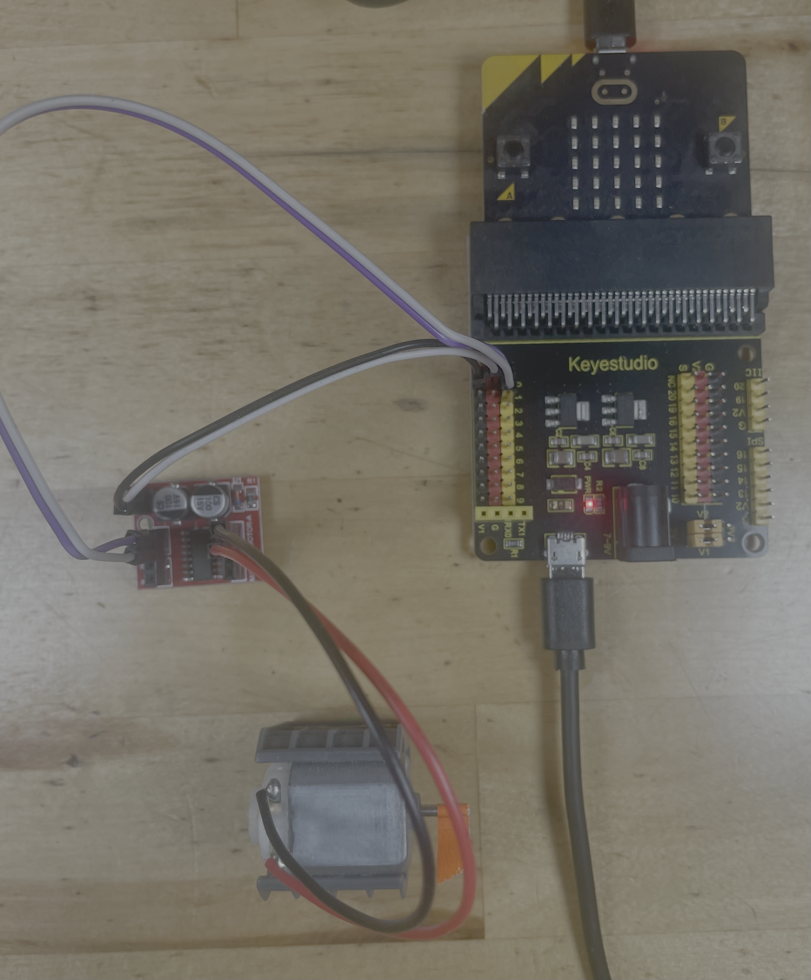
Our driver board has two h-bridges on it, which is very useful for a robot with two wheels. However, we will only us one of them. Using dupont wires, make these connections:
INT1( orINT3) to P0 signal ( yellow )INT2( orINT4zxsdx ) to P1 signal (yellow )Gnd to P0 ground. ( - )
Vcc to P0 power ( + )
Warning
Very Important! Connect the power pin Vcc last, and disconnect it first. Do not connect or disconnect the signal pins while power is applied. Violating these rules can destroy the driver.
It would be best to unplug both USB cables while connecting or disconnecting the H-Bridge
Then, connect the red and black motor leads to the “motor a” terminals. It doesn’t matter which side the red and black go on; swapping them will make the motor turn in the other direction when you program it to go forward. You may have to use a breadboard to make the connections between male Dupont wires.
Program
If you previous program – the Python program that changes the duty cycle – is still running, your motor may start moving, and speed up or slow down befor starting again. This is the result of the changing duty cycle setting the speed of the motor.
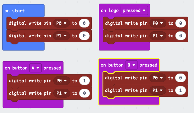
Here is a suggested program, but you can write a different program if you’d
like. The important part is that to go one direction, write a 0 to P0 and 1 to
P1. To reverse, write a 1 to P0 and a 0 to P1. This program will have a constant
speed, but you can modify it with analog write to drive the motor with a
variable speed.
( You can import this program from Github with the url https://github.com/League-Microbit/H-Bridge-Control.git)
After downloading the program, press the A button to turn the motor one direction, the B button to turn it the other, and the logo ( the robot face between the buttons ) to stop the motors.
Here is another program that shows how to change the speed of the motor, using
the analog write command.
( You can import this program from https://github.com/League-Microbit/duty-cycle-buttons )
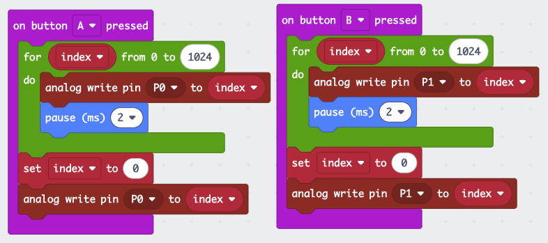
When you press the A or B buttons, this program will write a square wave duty cycle signal to the h-bridge, using the analog write feature, which will start the motor running slowly, then speed it up.
How it Works
If you’d like to know about how the brushed motor works, this video will explain all of the details.